Switching Techniques in Computer Networks
In the previous chapter, we looked at Multiplexing and how multiple independent signals can share a single physical link at the same time. Once several signals or users are already sharing the same network, another question naturally follows: once data reaches an intermediate point in the network, how does the network actually decide which path it should take to reach its final destination? This brings us to Switching Techniques, the methods networks use to move data from a sender to a receiver through a series of intermediate nodes.
A large network is rarely made up of just one direct wire connecting every sender to every possible receiver. Instead, data usually has to pass through a series of intermediate switching devices before it reaches its destination. A switching technique defines exactly how these intermediate devices handle and forward the data passing through them, and different techniques make very different trade-offs between setup time, reliability, and efficient use of network resources.
What is Switching in a Network?
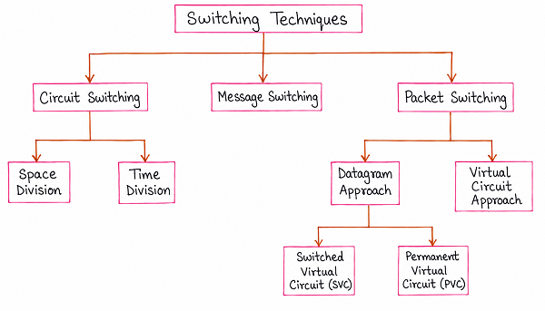
The diagram above organises the major switching techniques used in computer networks. At the top level, there are three broad categories: Circuit Switching, Message Switching, and Packet Switching. Circuit Switching is further divided into Space Division Switching and Time Division Switching, while Packet Switching is divided into the Datagram Approach and the Virtual Circuit Approach, with the Virtual Circuit Approach itself split into Switched Virtual Circuit (SVC) and Permanent Virtual Circuit (PVC). Each of these techniques is explained individually below.
Circuit Switching
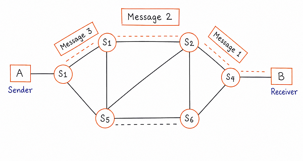
In Circuit Switching, a dedicated communication path is established between the sender and the receiver before any actual data transfer begins. This path is set up by reserving a specific sequence of physical links and switches through the network, and once established, that same path remains exclusively reserved for this one connection for as long as the communication continues, even during moments when no data is actually being sent. Once the communication finishes, the path is released and its resources become available for other connections. The traditional telephone system is the most familiar real-world example of circuit switching, since a dedicated line is reserved for the duration of a phone call.
As shown in the diagram, Circuit Switching itself can be implemented using either of two underlying technologies: Space Division Switching and Time Division Switching.
Space Division Switching
Space Division Switching creates a dedicated physical path by using separate, physically distinct sets of wires or circuit paths inside the switch for each connection. In this approach, every possible connection between an incoming line and an outgoing line has its own separate electrical path through the switching hardware, so a connection occupies a physically distinct portion of the switch for as long as it lasts. Because each connection uses genuinely separate hardware paths, space division switches can handle multiple simultaneous connections without any of them competing for the same physical circuitry.
Time Division Switching
Time Division Switching, on the other hand, achieves the same dedicated-connection behaviour without needing entirely separate physical paths for every connection. Instead, it combines circuit switching with time division multiplexing, sharing a single physical path among multiple connections by giving each connection its own repeating time slot. Even though multiple connections technically pass through the same underlying hardware, each connection is still guaranteed its own slot in every cycle, so from the perspective of the two communicating devices, it still behaves like a dedicated, continuously available path.
Message Switching
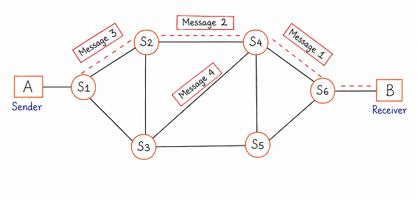
Message Switching takes a very different approach from Circuit Switching. Instead of reserving a dedicated path in advance, an entire message is sent as one complete unit from the sender to the first intermediate switch, where it is stored temporarily before being forwarded to the next switch along the way, and this store-and-forward process repeats at every intermediate node until the message finally reaches the receiver. Because of this behaviour, Message Switching is often described as a "store-and-forward" technique.
As shown in the diagram, since no fixed path is reserved ahead of time, different messages travelling between the same sender and receiver can end up taking entirely different routes through the network, depending on which paths are available or least busy at the time each message is forwarded. This makes the network more flexible and resilient, since a busy or failed link does not block communication entirely, as an alternate route can simply be used for the next message. However, since each intermediate switch must fully receive and store an entire message before forwarding it onward, Message Switching can introduce noticeable delays, and every intermediate switch also needs enough storage capacity to hold complete messages, which can become impractical for very large messages. For these reasons, Message Switching is largely considered an older technique historically associated with systems like telegraph networks, and it has mostly been replaced by Packet Switching in modern networks.
Packet Switching
Packet Switching addresses the main limitations of Message Switching by breaking a large message down into smaller, fixed-size units called packets before transmission, instead of sending the entire message as one single block. Each packet is transmitted independently through the network and is only briefly held at each intermediate switch before being forwarded onward, rather than requiring the switch to store an entire large message at once. Because packets are much smaller than complete messages, they move through the network more quickly and place a far lighter storage burden on each intermediate switch.
As shown in the earlier diagram, Packet Switching is implemented using one of two different approaches: the Datagram Approach and the Virtual Circuit Approach. These two approaches differ mainly in whether every packet is routed independently, or whether all packets belonging to the same message follow one shared, pre-determined path.
Datagram Approach
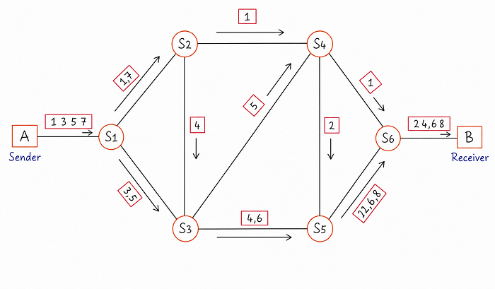
In the Datagram Approach, every packet belonging to the same message is treated as a completely independent unit and is routed through the network on its own, without any regard for the path taken by the other packets from the same message. As shown in the diagram, packets numbered 1, 2, 3, and 4, travelling from sender A to receiver B, can each be sent along a different route through the intermediate switches, depending on which path is available or most efficient at that particular moment.
Because each packet may take a different route and may experience different delays along the way, packets belonging to the same message can easily arrive at the receiver in a different order than they were originally sent, as illustrated by the packet order shown near the receiver in the diagram. To handle this, every packet in the Datagram Approach carries a sequence number, allowing the receiving device to correctly reorder all the packets back into the original message once every packet has arrived. This approach makes efficient use of available network paths and adapts well to changing network conditions, since packets can be automatically rerouted around a busy or failed link.
Virtual Circuit Approach
In the Virtual Circuit Approach, a single logical path is established between the sender and the receiver before actual data transfer begins, and every packet belonging to that same message then follows this exact same path through the network, one after another, as shown in the diagram. Unlike Circuit Switching, this path is not a physically dedicated set of resources reserved for the entire duration of the connection; it is a logical route that the network remembers and consistently reuses for every packet of that particular communication.
Because every packet from the same message follows the identical route, packets are guaranteed to arrive at the receiver in the exact same order in which they were sent, removing the need for the receiver to reorder them, unlike in the Datagram Approach. This predictability makes the Virtual Circuit Approach well suited to applications where maintaining the original sequence of data is important. The Virtual Circuit Approach itself is implemented in two different ways, based on how long that logical path remains set up.
Switched Virtual Circuit (SVC)
A Switched Virtual Circuit is established on demand, specifically for one particular communication session between a sender and a receiver. Before any data is transferred, a setup phase establishes the logical path through the network, and once the communication is complete, that path is torn down and its resources are released for use by other connections. This makes SVC well suited to temporary or occasional communication sessions, similar in spirit to how a phone call is set up only when needed and disconnected once finished.
Permanent Virtual Circuit (PVC)
A Permanent Virtual Circuit, in contrast, is a logical path that is set up in advance and left in place on a long-term basis, rather than being created fresh for every individual communication session. Since the path already exists whenever it is needed, data transfer can begin immediately without going through a separate setup phase each time. PVC is typically used between two points that need to exchange data frequently and regularly, where the overhead of repeatedly setting up and tearing down a path for every session would be unnecessary and inefficient.
Comparison of Switching Techniques
| Technique | Path Setup | Data Unit | Order of Arrival |
|---|---|---|---|
| Circuit Switching | Dedicated path reserved before communication begins | Continuous stream of data | Always in order, since only one fixed path is used |
| Message Switching | No path reserved; store-and-forward at each node | Entire message as one unit | Can vary, since different messages may take different paths |
| Packet Switching (Datagram) | No fixed path; each packet routed independently | Small, fixed-size packets | May arrive out of order and need reordering |
| Packet Switching (Virtual Circuit) | Logical path established once, reused by all packets | Small, fixed-size packets | Always in order, since all packets follow the same path |
Best Practices While Learning Switching Techniques
- Start with the three top-level categories — Circuit, Message, and Packet Switching — before going into their individual subtypes.
- Remember that Circuit Switching reserves a physical path, while Message and Packet Switching do not, which is the key distinction driving most of their other differences.
- Connect the Datagram Approach and Virtual Circuit Approach to a single question: does every packet choose its own path, or do all packets follow one shared path?
- Keep SVC and PVC straight by focusing on duration — SVC is set up per session, while PVC stays established long-term.
- Practice sketching the network diagrams for each technique, since exam questions often ask you to trace how a message or packet travels through a given network.
Common Mistakes Beginners Make
| Mistake | Correct Practice |
|---|---|
| Assuming Message Switching and Packet Switching are the same thing. | Message Switching sends an entire message as one unit, while Packet Switching breaks it into smaller packets. |
| Thinking the Virtual Circuit Approach reserves physical resources like Circuit Switching does. | Virtual Circuit only establishes a logical, reused path; it does not permanently reserve physical hardware for the connection. |
| Confusing SVC with PVC. | SVC is created fresh for each communication session; PVC remains permanently established for repeated use. |
| Assuming Datagram Approach packets always arrive in order. | Since each packet can take a different path, packets may arrive out of order and must be reordered using sequence numbers. |
Frequently Asked Interview Questions
-
What are the three main switching techniques used in computer networks?
The three main switching techniques are Circuit Switching, Message Switching, and Packet Switching. -
What is the key difference between Circuit Switching and Packet Switching?
Circuit Switching reserves a dedicated physical path for the entire duration of a connection, while Packet Switching breaks data into packets that share network resources dynamically without a permanently reserved path. -
What are the two technologies used to implement Circuit Switching?
Circuit Switching can be implemented using Space Division Switching, which uses physically separate paths for each connection, or Time Division Switching, which shares a physical path using dedicated time slots. -
Why is Message Switching called a store-and-forward technique?
Because each intermediate switch fully receives and stores an entire message before forwarding it to the next switch along the path. -
What is the difference between the Datagram Approach and the Virtual Circuit Approach in Packet Switching?
In the Datagram Approach, each packet is routed independently and may take a different path, while in the Virtual Circuit Approach, all packets follow a single pre-established logical path. -
Why might packets arrive out of order in the Datagram Approach?
Because each packet can travel through a different route with different delays, so packets sent later may sometimes arrive before packets sent earlier. -
What is the difference between a Switched Virtual Circuit and a Permanent Virtual Circuit?
A Switched Virtual Circuit is set up on demand for a single communication session and torn down afterward, while a Permanent Virtual Circuit remains established on a long-term basis for repeated use.
Summary
Switching techniques determine exactly how data actually moves through a network once it leaves the sender. We looked at Circuit Switching, which reserves a dedicated path using either Space Division or Time Division technology; Message Switching, which stores and forwards entire messages hop by hop without a fixed path; and Packet Switching, which breaks messages into smaller packets and routes them either independently through the Datagram Approach or along a shared logical path through the Virtual Circuit Approach, itself split into Switched and Permanent Virtual Circuits.
With a clear understanding of how switching techniques move data through a network, you are now ready to move on to error detection and correction, which explains how a network identifies and handles the inevitable errors that can occur while data travels across these paths.