Error Detection & Correction in Computer Networks
In the previous chapter, we looked at Switching Techniques and how data actually moves through a network from sender to receiver. However, no transmission medium is perfect. Electrical noise, signal attenuation, interference from nearby devices, and even tiny physical imperfections in cables or wireless channels can all cause the bits that arrive at the receiver to differ from the bits that were originally sent. Error Detection and Correction is the set of techniques networks use to identify when this kind of corruption has happened, and in some cases, to fix it without needing the data to be resent.
Without some way of catching these errors, a corrupted bit could silently change the meaning of a message, a file, or even a financial transaction, without either the sender or the receiver ever knowing something went wrong. This is why virtually every layer of a modern network, from the physical hardware up through application-level protocols, includes some mechanism for detecting or correcting errors before the data is trusted and used further.
Types of Errors
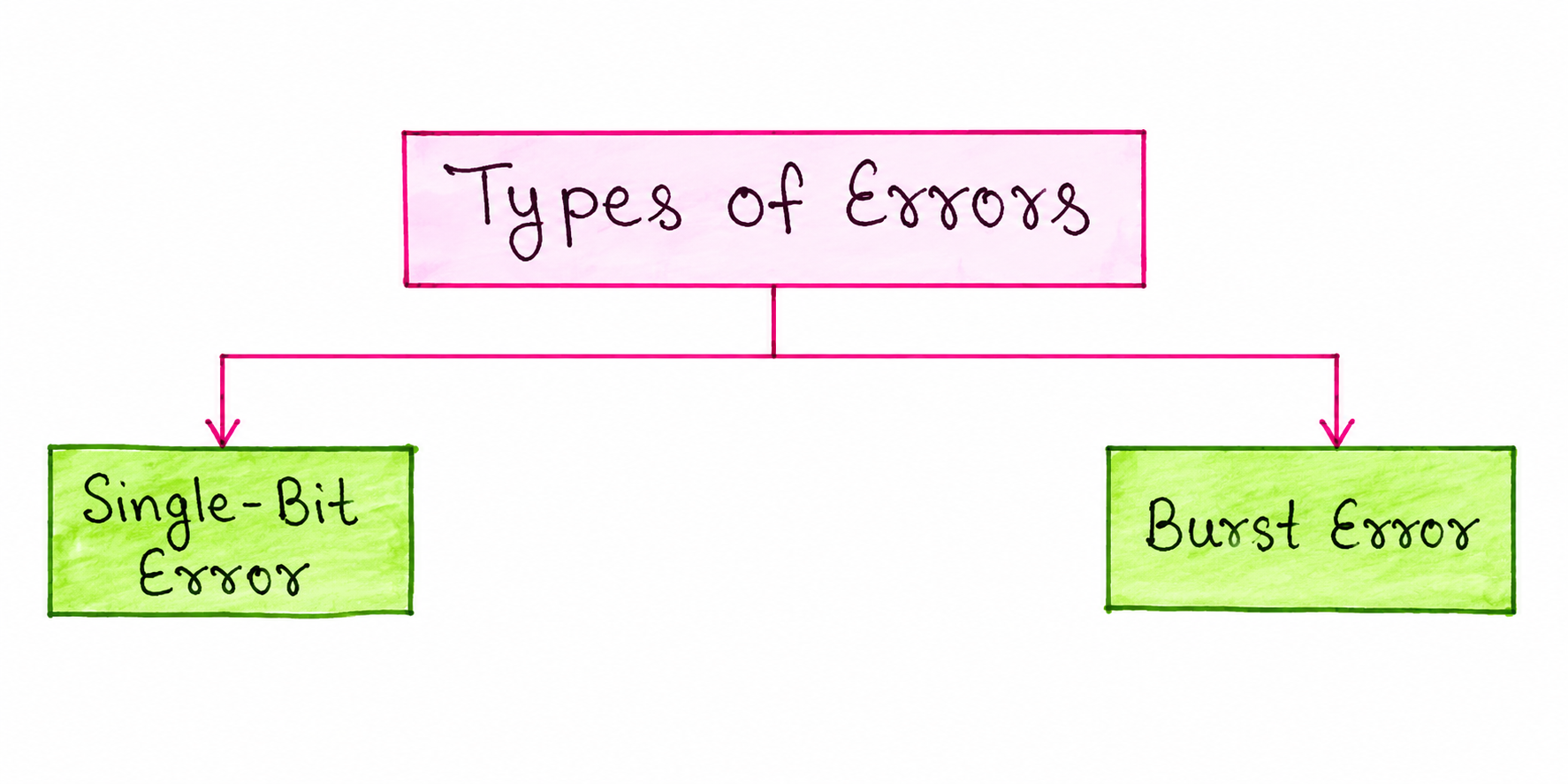
Errors that occur during data transmission are broadly classified into two categories, based on how many bits within the transmitted data are affected: Single-Bit Error and Burst Error. The technique needed to reliably catch an error often depends on which of these two categories that error falls into, which is why understanding both is an important starting point before looking at the actual detection methods.
Single-Bit Error
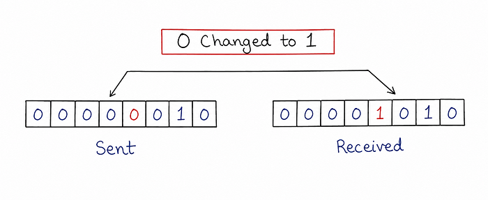
A Single-Bit Error occurs when only one single bit within a given data unit is altered during transmission, flipping from 0 to 1 or from 1 to 0, while every other bit in that same data unit arrives completely unchanged. As shown in the diagram, the data unit 00000010 is sent, but only one bit changes along the way, so the received data unit becomes 00001010. Single-bit errors are relatively rare in serial transmission over a single wire, since a brief burst of interference on a wire is more likely to disturb more than one consecutive bit, but they can occur more easily in parallel transmission, where each bit travels on its own separate wire.
Burst Error
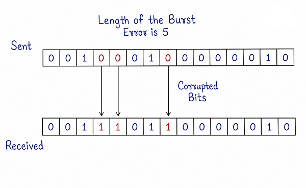
A Burst Error occurs when two or more consecutive bits within a data unit are corrupted during transmission. The length of a burst error is measured from the very first corrupted bit to the very last corrupted bit within that stretch, including any bits in between that happen to still be correct. As shown in the diagram, if the first corrupted bit and the last corrupted bit are five positions apart, the burst error is said to have a length of 5, even though not every single bit inside that stretch is necessarily wrong. Burst errors are far more common than single-bit errors in real networks, since a single spike of electrical noise, a brief signal fade, or interference typically lasts long enough to affect several consecutive bits at once, rather than just one.
Error Detection Techniques
Once the types of errors that can occur are understood, the next step is looking at the actual techniques networks use to catch them. The most widely used error detection techniques are Parity Check, Checksum, and Cyclic Redundancy Check (CRC). Each of these techniques works by adding some extra, calculated bits to the original data before it is sent, which the receiver can then use to verify whether the data arrived correctly.
Parity Check
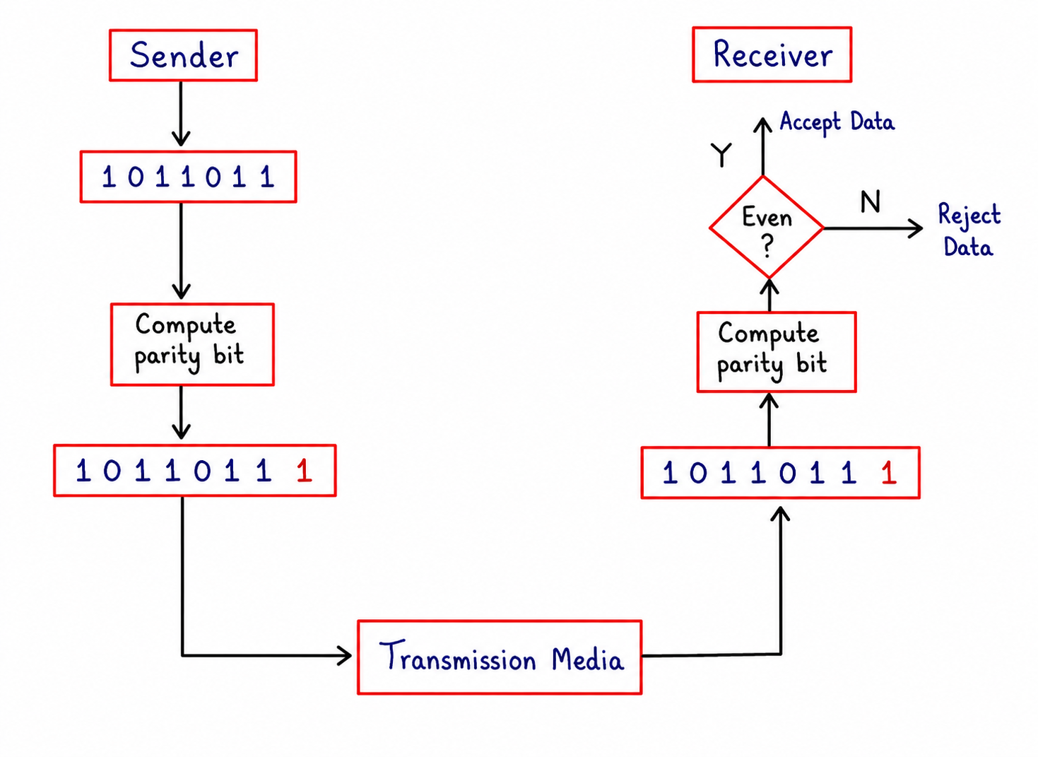
Parity Check is one of the simplest error detection techniques. Before sending a block of data, the sender counts the number of 1 bits in that data and computes one additional bit, called the parity bit, chosen specifically so that the total number of 1 bits, including this new parity bit, becomes even. As shown in the diagram, the sender computes this parity bit and appends it to the original data before transmitting the combined result across the transmission media.
At the receiving end, the receiver performs the very same calculation on the data it actually received, counting the total number of 1 bits, including the parity bit that was sent along with it. If that total count comes out even, the receiver accepts the data as correctly received. If the count comes out odd instead, the receiver knows that at least one bit was flipped somewhere during transmission, and the data is rejected. This particular version, where the parity bit is chosen to make the total count of 1s even, is known as even parity, though an equivalent odd parity scheme also exists.
Single Parity Check
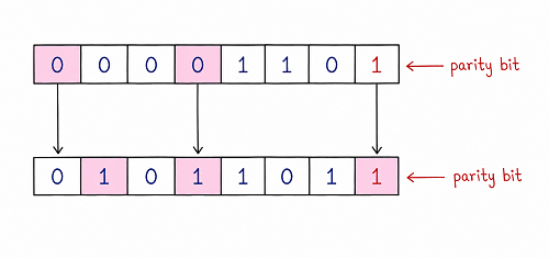
Single Parity Check refers to using just one parity bit for an entire block of data, as shown in the diagram. While this approach works well for catching a single-bit error, since flipping any one bit will always change the total count of 1s from even to odd, it has an important limitation: if exactly two bits happen to flip during transmission, the total count of 1s returns to being even again, and the error passes through completely undetected. Because of this, Single Parity Check is only reliable at catching errors that affect an odd number of bits, making it a fairly weak safeguard on its own against burst errors, which commonly affect multiple consecutive bits at once.
Multi Parity Check (Two-Dimensional Parity Check)
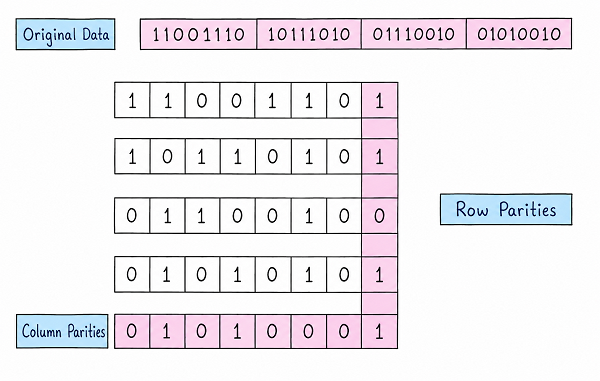
Multi Parity Check, also known as Two-Dimensional Parity Check, improves on the limitations of Single Parity Check by arranging the data into a grid of rows and columns instead of treating it as one single long block. As shown in the diagram, the original data is split into several equal-length rows, and a row parity bit is calculated and appended to the end of every individual row. In addition, a completely separate column parity row is calculated underneath the entire grid, where each column parity bit is computed from all the bits directly above it in that same column.
This two-dimensional arrangement gives the receiver far more information to work with than a single parity bit alone. If a bit gets corrupted, both its row parity and its column parity will no longer match what is expected, and since the row and column together point to one specific intersection point in the grid, Two-Dimensional Parity Check can often not only detect that an error occurred, but also pinpoint the exact bit position responsible for it, making limited error correction possible in addition to detection. This makes Multi Parity Check considerably more reliable than Single Parity Check, particularly for catching burst errors that affect multiple bits at once.
Checksum
Checksum is another widely used error detection technique, commonly used at higher layers of a network, such as in transport-layer protocols. To generate a checksum, the sender divides the data into several equal-sized segments and adds all of these segments together using a form of binary addition, wrapping any final carry bit back around into the result. The sender then complements this sum to produce the checksum value, which is appended to the original data before it is transmitted.
At the receiving end, the receiver performs the same addition process on the received data, this time including the checksum value itself as one of the segments being added. If none of the bits were corrupted during transmission, this final sum, once complemented, should come out to be entirely zero. If the result is not zero, the receiver knows the data has been corrupted somewhere along the way and rejects it. Because checksums operate on larger chunks of data at once rather than individual bits, they are well suited to catching a wide range of transmission errors with comparatively little computational overhead.
Cyclic Redundancy Check (CRC)
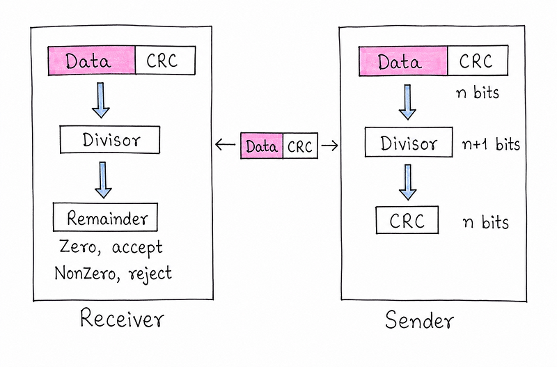
Cyclic Redundancy Check, commonly abbreviated as CRC, is considered one of the most powerful and widely used error detection techniques, and it works using a concept of binary polynomial division rather than simple bit counting or addition. As shown in the diagram, the sender first appends a fixed number of zero bits to the end of the original data, and then divides this extended data by a pre-agreed value called the divisor, using a special form of binary division. The remainder left over from this division, which is exactly as many bits long as the number of zero bits that were originally appended, becomes the CRC value. This CRC is then attached to the original data in place of the zero bits, and the combined result, containing both the original data and its CRC, is what actually gets transmitted.
At the receiving end, the receiver takes the entire block it received, including the appended CRC, and divides it by that very same divisor used by the sender. As shown in the diagram, if this division produces a remainder of zero, the receiver accepts the data as correctly received, confident that no bits were altered along the way. If the remainder comes out non-zero instead, the receiver concludes that the data was corrupted during transmission and rejects it. Because CRC is based on polynomial division rather than simple addition, it is particularly effective at catching burst errors, which is one of the main reasons it is so widely used in real networking hardware and protocols, including Ethernet.
Comparison of Error Detection Techniques
| Technique | How It Works | Strength Against Burst Errors |
|---|---|---|
| Single Parity Check | One parity bit makes the total count of 1s even (or odd) | Weak — fails if an even number of bits flip together |
| Multi Parity Check | Row and column parity bits form a two-dimensional grid | Better — can often detect and locate a single corrupted bit |
| Checksum | Segments of data are added together and complemented | Moderate to good, depending on segment size and error pattern |
| Cyclic Redundancy Check (CRC) | Data is divided by a fixed divisor using polynomial division | Strong — specifically effective at catching burst errors |
Best Practices While Learning Error Detection
- Start by clearly separating Single-Bit Errors from Burst Errors, since the reliability of each technique depends heavily on which type of error it is being tested against.
- Walk through the Single Parity Check example by hand and try flipping two bits instead of one, to see for yourself why it fails to catch certain errors.
- Practice building a small Two-Dimensional Parity grid, since exam questions often ask you to identify the corrupted bit using the row and column parities together.
- Remember CRC as a division problem, not an addition problem — the remainder from dividing by the divisor is the entire basis of the technique.
- Keep in mind that detecting an error is not the same as correcting it — most of these techniques, apart from certain parity arrangements, only tell the receiver that data needs to be resent, rather than fixing it directly.
Common Mistakes Beginners Make
| Mistake | Correct Practice |
|---|---|
| Assuming Single Parity Check can catch any number of flipped bits. | Remember it only reliably catches an odd number of flipped bits, and fails when exactly two bits flip together. |
| Confusing the length of a burst error with the number of bits that are actually wrong. | Burst error length is measured from the first to the last corrupted bit, even if some bits in between are still correct. |
| Thinking CRC works using simple addition like a checksum. | CRC is based on binary polynomial division, and the remainder from that division is what forms the CRC value. |
| Assuming every error detection technique also corrects the error. | Most techniques, including CRC and Checksum, only detect that an error occurred and typically require the data to be retransmitted. |
Frequently Asked Interview Questions
-
What is the difference between a Single-Bit Error and a Burst Error?
A Single-Bit Error affects only one bit within a data unit, while a Burst Error affects two or more consecutive bits between the first and last corrupted bit positions. -
Why does Single Parity Check fail to detect certain errors?
Because if exactly two bits flip during transmission, the total count of 1 bits returns to being even again, making the error undetectable using a single parity bit. -
How does Two-Dimensional Parity Check improve on Single Parity Check?
By arranging data into rows and columns with separate parity bits for each, it can often not only detect an error but also locate the exact corrupted bit using the intersection of the affected row and column. -
How is a checksum calculated?
The sender divides the data into equal-sized segments, adds them together, and complements the result to form the checksum, which the receiver later uses by repeating the same addition and checking whether the result is zero. -
Why is CRC considered more powerful than simple parity checks?
Because CRC uses polynomial division rather than simple bit counting, which makes it especially effective at reliably detecting burst errors that affect multiple consecutive bits. -
What does it mean if the CRC remainder at the receiver is non-zero?
It means the data was altered somewhere during transmission, so the receiver rejects the data instead of accepting it. -
Do error detection techniques always correct the error automatically?
No, most techniques such as CRC and Checksum only detect that an error has occurred, and the corrupted data usually needs to be retransmitted rather than being automatically fixed.
Summary
Error Detection and Correction ensures that a network can reliably tell whether the data it received actually matches the data that was originally sent. We looked at the two broad types of errors, Single- Bit and Burst, along with the major detection techniques used to catch them: Parity Check, in both its Single and Two-Dimensional forms, Checksum, and Cyclic Redundancy Check, each offering a different balance between simplicity and reliability, particularly when it comes to catching burst errors.
With a solid understanding of how errors are detected during transmission, you are now ready to move on to network devices, which explains the physical hardware, such as routers, switches, and hubs, that actually forms the network these error detection techniques operate across.