Multiplexing in Computer Networks
In the previous chapter, we looked at the TCP/IP Model and how real-world networks actually implement communication between devices. One question that naturally follows is how so many independent signals, from thousands of different users and devices, manage to travel across a limited number of physical links at the same time. This brings us to Multiplexing, a technique that allows multiple signals coming from different sources to share a single transmission link simultaneously, instead of each signal requiring its own separate physical medium.
Multiplexing is used extensively in real communication systems — telephone networks, radio and television broadcasting, satellite communication, and fiber-optic internet backbones all rely on some form of multiplexing to carry enormous amounts of data efficiently over a limited number of physical links. Without multiplexing, the cost and complexity of laying separate cables or allocating separate channels for every single conversation or data stream would make large-scale communication networks practically impossible to build.
What is a Multiplexer (MUX) and a Demultiplexer (DEMUX)?
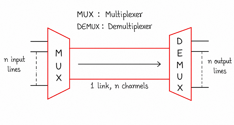
The diagram above shows the basic idea behind multiplexing. At the sending end, a device called a multiplexer, commonly written as MUX, takes signals coming in from several independent input lines and combines them into a single output signal. This combined signal is then sent across one shared communication link. At the receiving end, a corresponding device called a demultiplexer, or DEMUX, performs the exact opposite job — it takes the single combined signal arriving over the link and separates it back into the original individual signals, delivering each one to its correct destination line.
This relationship is often summarised with a simple rule, shown in the diagram itself: if there are n independent input lines feeding into the multiplexer, then only one physical link is required between the multiplexer and the demultiplexer, but that single link is capable of carrying n separate channels of information. In other words, one shared link ends up doing the work of n separate links, which is precisely what makes multiplexing so valuable from both a cost and an efficiency standpoint.
Types of Multiplexing
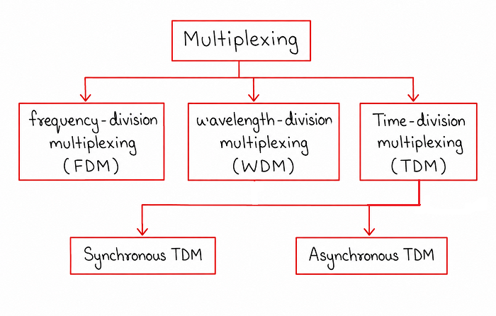
The diagram above organises multiplexing into three major techniques, based on how each one divides up the shared link so that multiple signals can travel across it without interfering with one another: Frequency Division Multiplexing (FDM), Wavelength Division Multiplexing (WDM), and Time Division Multiplexing (TDM). As the diagram shows, Time Division Multiplexing is further split into two categories, Synchronous TDM and Asynchronous TDM. FDM and WDM divide the available bandwidth of the link, while TDM divides the available transmission time. The sections below walk through each of these techniques individually.
1. Frequency Division Multiplexing (FDM)
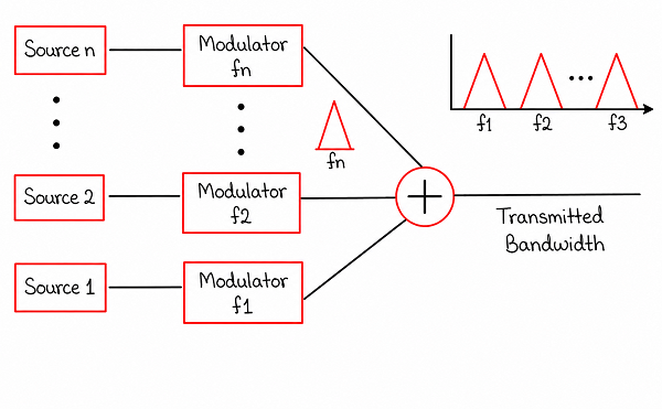
Frequency Division Multiplexing works by dividing the total available bandwidth of the shared communication link into a number of smaller, non-overlapping frequency bands, and then assigning one such frequency band to each individual signal source. As shown in the diagram, every source is first passed through a modulator, which shifts that source's signal onto its assigned carrier frequency. For example, if there are n sources, the first source is modulated onto carrier frequency f1, the second onto f2, and so on up to fn for the last source.
Once each source has been modulated onto its own distinct carrier frequency, all of these modulated signals are combined together using a summing circuit, producing a single composite signal that contains every source's data, each occupying its own separate slice of the frequency spectrum. This combined signal is what actually travels across the shared transmission link, and the entire range of frequencies it occupies is referred to as the transmitted bandwidth. At the receiving end, a set of filters tuned to each specific carrier frequency separates the composite signal back into its individual components, recovering each original source's data.
To prevent adjacent frequency bands from overlapping and interfering with one another, small unused strips of frequency, called guard bands, are usually left between each assigned frequency band. FDM is fundamentally an analog multiplexing technique and is widely used in traditional radio broadcasting, where each radio station is assigned its own frequency band, as well as in analog television broadcasting and older telephone trunk systems.
2. Wavelength Division Multiplexing (WDM)
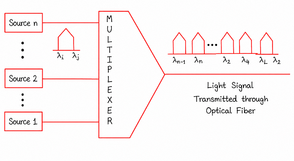
Wavelength Division Multiplexing is conceptually very similar to Frequency Division Multiplexing, except that it is designed specifically for use with fiber-optic communication, where data is transmitted as pulses of light rather than as electrical signals. Instead of assigning each source a distinct carrier frequency, WDM assigns each source a distinct wavelength of light, as shown in the diagram. Since wavelength and frequency are directly related properties of light, this is essentially the same underlying idea as FDM, just applied to the optical domain.
In a WDM system, multiple sources, each transmitting its own beam of light at a unique wavelength, are fed into an optical multiplexer. The multiplexer combines all of these individual light beams into a single composite light signal, which is then transmitted through one single optical fiber cable, as the diagram illustrates. Because a single fiber can carry many wavelengths simultaneously without them interfering with each other, WDM dramatically increases the amount of data a single fiber-optic cable can carry at once, without requiring any additional physical cabling.
At the receiving end of the fiber, an optical demultiplexer separates the composite light signal back into its individual wavelength components, directing each one to its corresponding receiver. WDM is the core technology behind modern high-capacity fiber-optic internet backbones, allowing internet service providers to transmit enormous volumes of data across long distances using relatively few physical fiber strands.
3. Time Division Multiplexing (TDM)
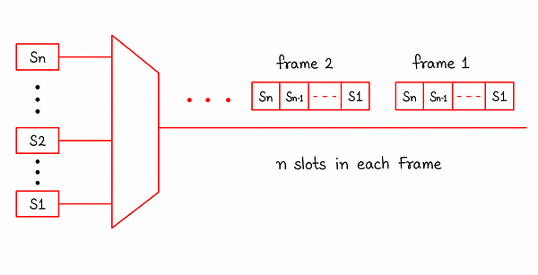
Unlike FDM and WDM, which separate signals by giving each one a different portion of the frequency or wavelength spectrum, Time Division Multiplexing separates signals by giving each one a different slice of time on the same shared link. In TDM, the entire bandwidth of the link is available to every source, but each source is only allowed to transmit during its own designated time slot, taking turns with the other sources in a repeating cycle.
As shown in the diagram, the shared timeline of the link is divided into repeating units called frames, and each frame is further divided into a fixed number of smaller units called time slots. If there are n sources sharing the link, each frame typically contains n time slots, with exactly one slot in every frame reserved for each source. As one frame ends, a new frame immediately begins, and the same round-robin pattern of slot allocation repeats continuously for as long as the sources need to transmit.
Because a receiver only needs to know which time slot belongs to which source, and every sender and receiver stays synchronised to the same frame structure, TDM works entirely in the digital domain and is the multiplexing technique most commonly used in digital telephone networks and many digital data communication systems.
3a. Synchronous TDM
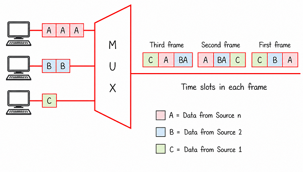
In Synchronous TDM, every source connected to the multiplexer is given a fixed, pre-assigned time slot in every single frame, regardless of whether that source actually has any data ready to send at that moment. As shown in the diagram, if three sources, A, B, and C, are sharing a link using Synchronous TDM, then every frame will always contain a slot reserved for each of them, in a fixed and repeating order, no matter how much or how little data each source actually generates at that time.
This fixed allocation makes Synchronous TDM simple to implement and easy to predict, since the multiplexer never needs to check whether a source is active before assigning it a slot. However, the major drawback is that if a source has no data to send during its turn, its reserved slot is transmitted empty anyway, wasting that portion of the link's capacity. This means Synchronous TDM can be inefficient whenever sources generate data at uneven or unpredictable rates, since idle slots cannot be reassigned to a busier source.
3b. Asynchronous TDM (Statistical TDM)
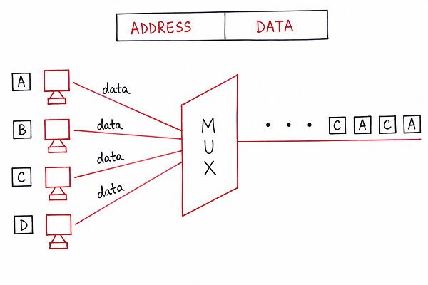
Asynchronous TDM, also called Statistical TDM, addresses the main weakness of Synchronous TDM by allocating time slots dynamically rather than following a fixed, pre-assigned schedule. Instead of reserving a slot for every source in every single frame, the multiplexer only allocates a slot to a source when that source actually has data ready to transmit. Sources that are idle at a given moment simply do not receive a slot in that frame, freeing up that capacity for sources that are actively sending data.
Since the number of active sources can vary from one frame to the next, each data unit in Asynchronous TDM must carry an address or identifier indicating which source it belongs to, so the demultiplexer at the receiving end knows where to deliver it. This extra addressing information adds a small amount of overhead compared to Synchronous TDM, but the overall gain in efficiency is usually far greater, since the link's capacity is used only by sources that genuinely need it at that moment, rather than being wasted on idle slots.
Why Multiplexing Matters in Computer Networks
Multiplexing is one of the core ideas that makes large-scale, cost-effective communication networks possible. Physical transmission links, whether copper cables, optical fibers, or wireless spectrum, are expensive resources to install and maintain, and their raw capacity is almost always far greater than what a single signal actually needs. Multiplexing allows network providers to make full use of that available capacity by packing many independent signals onto the same link, instead of leaving most of that capacity unused.
This concept directly connects to other topics in Computer Networks. Transmission media, such as twisted pair, coaxial cable, and fiber optics, define how much raw bandwidth is physically available, while multiplexing techniques determine how efficiently that available bandwidth is actually shared among multiple users or data streams. Understanding multiplexing also makes it easier to grasp switching techniques in the next chapter, since both topics deal with how a network makes efficient use of shared, limited resources.
Comparison of FDM, WDM, and TDM
| Technique | Domain | How Signals Are Separated | Typical Use |
|---|---|---|---|
| FDM | Analog | Different carrier frequencies for each source | Radio broadcasting, analog TV, older telephone trunks |
| WDM | Optical | Different light wavelengths for each source | Fiber-optic internet backbones |
| Synchronous TDM | Digital | Fixed, pre-assigned time slots for each source | Digital telephone networks with steady data rates |
| Asynchronous TDM | Digital | Time slots assigned only to active sources | Data networks with variable or bursty traffic |
Best Practices While Learning Multiplexing
- Remember the core idea first: one shared link carrying n channels, instead of n separate physical links.
- Connect FDM and WDM together, since both share bandwidth by frequency or wavelength rather than by time.
- Practice drawing the frame and slot structure of TDM, since exam questions often ask you to identify slots for a given set of sources.
- Focus on the key trade-off between Synchronous and Asynchronous TDM: simplicity and predictability versus efficient use of idle time.
- Relate multiplexing to real systems you already know, such as how a single fiber-optic cable can carry an entire neighbourhood's internet traffic using WDM.
Common Mistakes Beginners Make
| Mistake | Correct Practice |
|---|---|
| Confusing multiplexing with switching. | Multiplexing shares one physical link among multiple signals; switching decides the path data takes through a network. |
| Assuming FDM and TDM work the same way. | FDM divides the link by frequency, while TDM divides the link by time; they solve the same problem differently. |
| Thinking Synchronous TDM is always better because it is simpler. | Synchronous TDM can waste capacity on idle slots, while Asynchronous TDM adapts to actual traffic. |
| Forgetting that WDM is essentially FDM applied to optical fiber. | Remember WDM separates signals by wavelength of light rather than electrical frequency. |
Frequently Asked Interview Questions
-
What is the main purpose of multiplexing in a network?
Multiplexing allows multiple independent signals to share a single transmission link at the same time, avoiding the cost and complexity of installing a separate physical link for every signal. -
What is the difference between a multiplexer and a demultiplexer?
A multiplexer combines multiple input signals into a single signal for transmission over a shared link, while a demultiplexer performs the reverse task, separating that combined signal back into its original individual signals at the receiving end. -
What is the difference between FDM and TDM?
FDM assigns each signal its own portion of the frequency spectrum, so all signals travel at the same time but on different frequencies, while TDM gives every signal the full frequency range but only during its own assigned time slot. -
Why is WDM important for fiber-optic networks?
WDM allows a single optical fiber to carry many independent light signals at once by assigning each one a different wavelength, massively increasing the data-carrying capacity of that one physical fiber without adding new cables. -
What is the main drawback of Synchronous TDM?
Since every source is given a fixed slot in every frame regardless of whether it has data ready, an idle source's slot is transmitted empty, wasting part of the link's capacity. -
Why does Asynchronous TDM need addressing information for each slot?
Since slots are assigned dynamically based on which sources are active, the demultiplexer has no fixed schedule to rely on, so each data unit must include an identifier showing which source it belongs to. -
What role do guard bands play in FDM?
Guard bands are small unused strips of frequency left between assigned frequency bands to prevent adjacent signals from overlapping and interfering with one another.
Summary
Multiplexing solves one of the most fundamental problems in networking: how to let many independent signals share a limited number of physical links efficiently. We looked at how a MUX combines n input lines into a single shared link while a DEMUX separates them back out at the receiving end, and then walked through the three major multiplexing techniques — FDM, which separates signals by frequency; WDM, which applies the same idea to light wavelengths over optical fiber; and TDM, which separates signals by time, further divided into Synchronous and Asynchronous TDM depending on how slots are allocated.
With a clear understanding of multiplexing, you are now ready to move on to switching techniques, which explains how a network actually decides the path that data takes once multiple signals are already sharing the available links.