Buses in Computer Organization
A computer contains several hardware units, including the processor, main memory, and input/output devices. These units must exchange addresses, data, and control information during almost every instruction cycle. A bus provides the communication path through which this information can be transferred between these components.
A bus is not simply a single wire. It is a group of parallel communication lines designed to carry a particular type of information. In a traditional system bus, the major groups are the data bus, address bus, and control bus. Each group performs a different role during communication between the CPU, memory, and I/O devices.
Understanding buses is important because bus width, direction, transfer mechanism, and control signals directly affect how a processor communicates with memory and peripheral devices.
System Bus Diagram
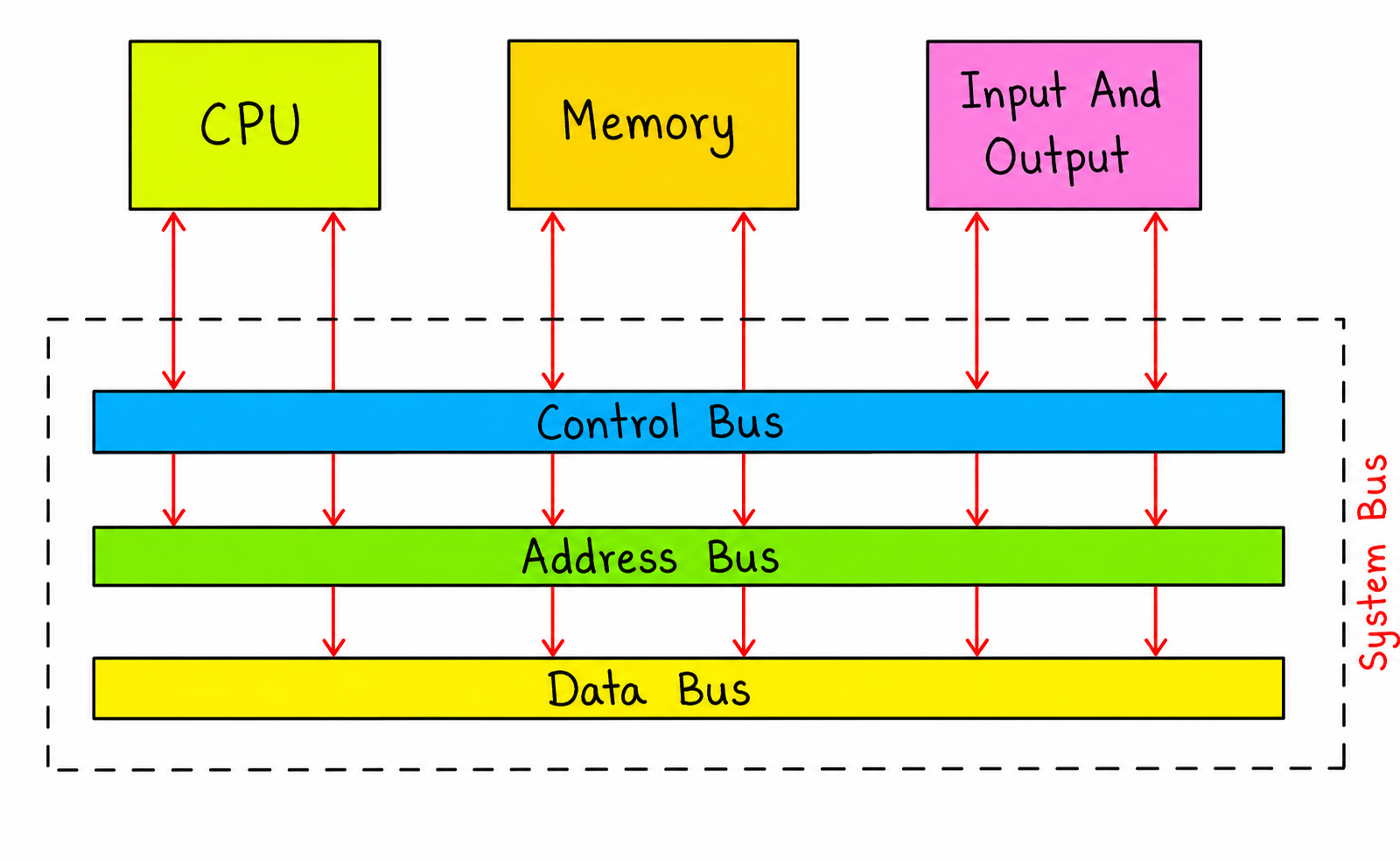
The diagram represents the traditional system-bus organization. The CPU communicates with memory and I/O devices through separate groups of lines carrying data, addresses, and control information.
What Is a Bus?
A bus is a set of electrical or logical communication lines used to transfer information between components of a computer system. Instead of connecting every hardware component directly to every other component, a shared bus provides a common communication path.
For example, when the CPU wants to read a value from memory, it needs to identify the memory location, specify that a read operation is required, and receive the requested data. These three requirements correspond to the address, control, and data portions of the bus system.
Basic Information Carried by a Bus
| Information | Purpose |
|---|---|
| Address | Identifies the memory or I/O location involved in an operation. |
| Data | Carries the actual value being transferred. |
| Control | Specifies and coordinates operations such as read, write, interrupt, and timing. |
Types of Buses in Computer Organization
The traditional system bus is commonly described using three functional groups:
- Data Bus – carries the actual data.
- Address Bus – identifies the source or destination address.
- Control Bus – carries signals that coordinate the operation.
These buses work together rather than operating independently. A typical memory transaction requires the CPU to place an address on the address lines, generate an appropriate control signal, and then transfer data through the data lines.
1. Data Bus
The data bus carries the actual binary information being transferred between the CPU, memory, and I/O devices. Depending on the architecture and transaction, data may travel toward the CPU or away from it.
For example, during a memory read operation, the memory sends the requested data to the processor through the data bus. During a memory write operation, the processor sends data to memory through the same communication path.
Data Bus Width
The width of a data bus represents the number of bits that can be transferred in parallel during a bus transfer. Common widths include 8, 16, 32, 64, and larger values.
For example, a 32-bit data bus can transfer up to 32 bits, or 4 bytes, in one parallel transfer. A 64-bit data bus can transfer up to 64 bits, or 8 bytes, in one such transfer.
32 bits = 4 bytes

64 bits = 8 bytes
Bus width should not be confused with CPU word size or overall system performance. Actual throughput also depends on clock frequency, transfer protocol, wait states, memory latency, and other architectural factors.
Characteristics of Data Bus
- Carries actual data values.
- Usually supports transfers in both directions.
- Its width determines the amount of data transferred per bus transfer.
- Connects processing, memory, and I/O components during data transactions.
2. Address Bus
The address bus carries the address that identifies the memory location or I/O location involved in a transaction. The processor uses these address lines to specify where a read or write operation should take place.
For a traditional CPU-to-memory interface, the processor normally places the required address on the address bus before the memory operation is performed.
Address Bus Width and Addressable Memory
The number of address lines determines how many distinct addresses can be represented. If a system has n address lines, it can represent up to:
2^n addresses
For example, a system with a 16-bit address bus can represent:
2^16 = 65,536 addresses
If each address identifies one byte, the directly addressable memory space would be 65,536 bytes, or 64 KB.
Similarly, a 32-bit address space can represent up to 2³² distinct byte addresses, giving a theoretical address space of 4 GiB when byte addressing is used.
Characteristics of Address Bus
- Identifies the location involved in a transfer.
- Traditionally described as unidirectional from the processor.
- The number of address lines determines the theoretical address space.
- Can be used for memory addressing and, depending on the architecture, I/O addressing.
3. Control Bus
The control bus carries signals that coordinate communication between the CPU, memory, and I/O devices. Unlike the data bus, these signals do not normally represent the actual value being transferred. Instead, they indicate what operation should occur and help coordinate when it occurs.
Examples of control-related signals include Read, Write, Interrupt, Clock, Reset, and other handshake or bus-control signals, depending on the architecture.
Examples of Control Signals
| Signal | Purpose |
|---|---|
| Read | Indicates that data should be obtained from the selected location. |
| Write | Indicates that data should be stored at the selected location. |
| Interrupt | Allows a device or hardware subsystem to request processor attention. |
| Reset | Places the system or a component into a defined initial state. |
| Clock | Provides timing information in systems where the bus uses a clocked protocol. |
The exact control signals differ between processor architectures and bus standards. Therefore, the control bus should be understood as a functional group of control and coordination signals rather than one fixed set of wires used by every computer.
System Bus
The combination of data, address, and control communication paths is commonly called the system bus. It provides the basic communication mechanism between the processor, main memory, and I/O subsystems in traditional bus-based computer organization.
A simplified view is:
              +----------------+
              |      CPU       |
              +----------------+
                      |
        --------------------------------
        |              |               |
     Address          Data           Control
        Bus            Bus             Bus
        |              |               |
        --------------------------------
             |                    |
       +-----------+       +-------------+
       |  Memory   |       | I/O Devices |
       +-----------+       +-------------+
The three functional groups cooperate during a transaction. The address identifies the location, the control signals specify the operation, and the data lines carry the value being transferred.
How a Memory Read Operation Works
Consider a simple situation in which the CPU wants to read data from a particular memory address. The operation can be understood in the following sequence.
- Address placement: The CPU places the required memory address on the address lines.
- Read control: The CPU activates the appropriate read control signal.
- Memory selection: The memory subsystem identifies the location represented by the address.
- Data transfer: The requested value is placed on the data bus and transferred toward the CPU.
- Completion: The processor receives the data and continues execution.
The actual sequence can be more complex in modern systems because caches, memory controllers, bus protocols, arbitration, and multiple clock cycles may be involved. The simplified sequence is useful for understanding the fundamental role of each bus.
How a Memory Write Operation Works
A memory write operation follows a similar process, but the direction of data transfer is reversed.
- The CPU places the destination address on the address lines.
- The CPU places the value to be stored on the data lines.
- The processor activates the appropriate write control signal.
- The memory subsystem stores the data at the selected address.
CPU
 |
 |---- Address ----> Memory
 |
 |---- Data -------> Memory
 |
 |---- Write ------> Memory
This illustrates why all three bus functions are important. The memory needs to know where the operation occurs, what value is involved, and which operation should be performed.
Bus Width
Bus width is an important characteristic of a bus because it indicates how many bits can be carried by the corresponding group of lines during a transfer.
| Bus | Width Indicates | Effect |
|---|---|---|
| Data Bus | Number of data bits transferred in parallel | Affects the amount of data transferred per bus transfer. |
| Address Bus | Number of address bits | Determines the theoretical number of addressable locations. |
| Control Bus | Number and type of control signals | Determines available control and coordination functions. |
A wider bus does not automatically mean that the entire computer is faster. Performance depends on several other factors, including clock rate, memory latency, bus protocol, cache behavior, and the number of transfers that can be completed per cycle.
Address Bus Example
Suppose a processor has 20 address lines and uses byte-addressable memory. The number of possible addresses is:
Number of addresses = 2^20

                  = 1,048,576 addresses
Since each address identifies one byte:
Addressable memory = 1,048,576 bytes

                   = 1 MB
This example demonstrates the relationship between address-bus width and theoretical addressable memory.
Data Bus Example
Suppose a processor has a 16-bit data bus. A single parallel transfer can carry:
16 bits = 2 bytes
If a larger 32-bit value has to be transferred and the interface can transfer only 16 bits at a time, multiple transfers may be required.
The exact number of transfers depends on the architecture and bus protocol, but the example demonstrates the basic relationship between bus width and transfer size.
Data Bus vs Address Bus vs Control Bus
| Feature | Data Bus | Address Bus | Control Bus |
|---|---|---|---|
| Purpose | Carries actual data | Identifies location | Controls and coordinates operations |
| Typical Direction | Both directions | Usually from processor toward the selected subsystem | Depends on the signal |
| Example | Integer or instruction data | Memory address | Read or Write |
| Width Represents | Bits transferred in parallel | Number of address bits | Available control signals |
| Main Role | Transfers the value | Selects the location | Defines the operation |
Bus-Based Communication Example
Consider a CPU instruction that requires a value stored in memory. At a simplified level, the processor must first identify the required memory location. The address is communicated through the address path. A read control signal indicates that the processor wants to obtain data. The memory subsystem then provides the requested value through the data path.
Step 1:
CPU → Address Bus → Memory

Step 2:
CPU → Read Signal → Memory

Step 3:
Memory → Data Bus → CPU
This example shows the complementary roles of the three bus groups: address selects the location, control specifies the operation, and data carries the value.
Limitations of Traditional Shared Buses
A shared bus provides an economical way to connect multiple components, but it also introduces limitations as the number and speed of connected devices increase.
- Bandwidth limitation: Multiple devices may compete for the same communication path.
- Bus contention: Only the appropriate device should drive a shared bus at a given time.
- Latency: A device may have to wait before it can use the bus.
- Scalability: Increasing the number of high-speed devices can make a shared bus difficult to scale efficiently.
- Electrical limitations: Higher speeds and longer physical connections introduce signal-integrity and timing challenges.
Modern computer systems therefore often use more specialized interconnects, point-to-point links, switched fabrics, and dedicated memory or I/O interfaces rather than relying entirely on one shared system bus.
Bus Arbitration
When multiple devices can request access to a shared bus, the system needs a mechanism to determine which device is allowed to use it. This process is called bus arbitration.
An arbitration mechanism prevents multiple devices from attempting to control the same shared communication lines simultaneously.
Depending on the architecture, arbitration may be centralized or distributed. The exact implementation varies among computer systems and bus standards.
Bus Performance Factors
Bus performance cannot be judged from bus width alone. Several characteristics influence the effective rate of communication.
| Factor | Meaning |
|---|---|
| Bus Width | Number of bits transferred in parallel. |
| Clock Frequency | Frequency at which clocked transfers can occur. |
| Transfer Rate | Number of transfers that can be completed over a period of time. |
| Latency | Time required before a requested transfer begins or completes. |
| Protocol | Rules governing communication, timing, and control between devices. |
For this reason, comparing two systems only by saying that one has a "wider bus" can be misleading. Effective performance depends on the complete communication architecture.
Key Points to Remember
- A bus provides a communication path between computer components.
- The traditional system bus is described using data, address, and control buses.
- The data bus carries the actual information being transferred.
- The address bus identifies the memory or I/O location involved in a transaction.
- The control bus carries signals that coordinate operations.
- Data-bus width affects the amount of data that can be transferred in parallel.
- Address-bus width determines the theoretical number of addressable locations.
- Bus arbitration is required when multiple devices compete for a shared communication path.
- Modern systems may use specialized and point-to-point interconnects instead of a single shared bus.
Frequently Asked Questions
1. What is a bus in Computer Organization?
A bus is a group of communication lines used to transfer information between components such as the CPU, memory, and I/O devices.
2. What are the three main types of system buses?
The three commonly described types are the Data Bus, Address Bus, and Control Bus.
3. What is the function of the data bus?
The data bus carries the actual data being transferred between the processor, memory, and I/O devices.
4. What is the function of the address bus?
The address bus identifies the memory or I/O location involved in a particular operation.
5. What is the function of the control bus?
The control bus carries signals that specify and coordinate operations such as read, write, interrupt, reset, and timing-related activities.
6. How does address-bus width affect memory?
With n address lines, a system can represent up to 2n distinct addresses. The resulting addressable memory depends on the addressing unit, such as bytes or words.
7. Why is a wider data bus useful?
A wider data bus can carry more bits in parallel during a transfer, potentially increasing the amount of data transferred per transaction.
8. What is bus arbitration?
Bus arbitration is the process of deciding which device is allowed to use a shared bus when multiple devices request access.
Conclusion
Buses provide the communication infrastructure through which computer components exchange addresses, data, and control information. In the traditional system-bus model, the address bus identifies the location, the data bus carries the actual value, and the control bus coordinates the operation.
Bus width and communication protocols influence how efficiently information can be transferred. The address-bus width determines the theoretical address space, while the data-bus width determines how many data bits can be transferred in parallel. When multiple devices share a bus, arbitration and timing mechanisms are required to coordinate access.
These concepts form an important foundation for understanding CPU-memory communication, I/O organization, memory systems, and modern computer interconnects.